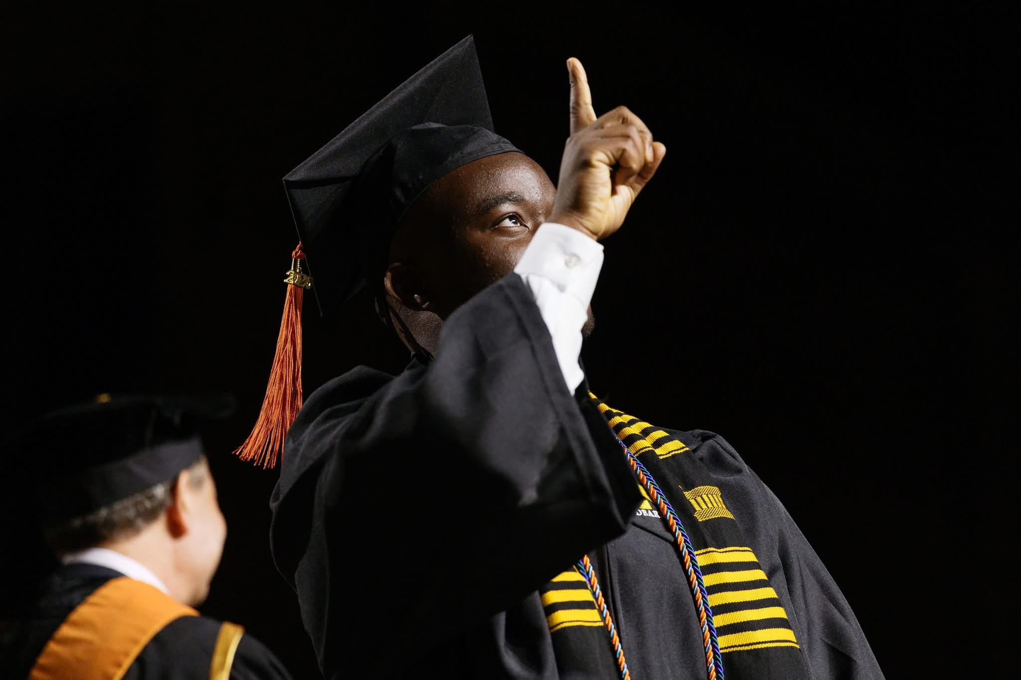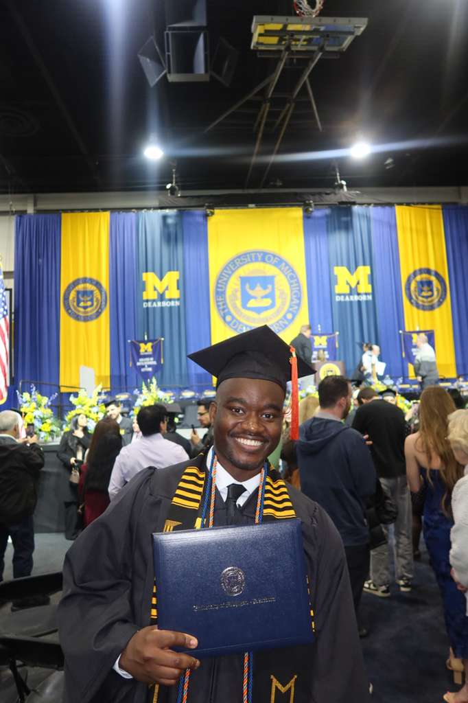
I'm a creative recent mechanical engineering grad with the drive to make a lasting impact through my work, and a habit of bringing ideas all the way into fruition. Through my experience designing a chest-supported lat machine from napkin sketch to a filed provisional patent, leading avionics bay design for my university's rocketry team, and running FEA crash models and CFD simulations during two internships at Altair Engineering (recently acquired by Siemens), I developed a deeper passion for both mechanical design and CAE. Currently, I'm studying for the Mechanical FE Exam on my way to a PE license, so that I can become a more well-rounded mechanical engineer.
Please keep scrolling: the projects below tell the story better than I can up here...
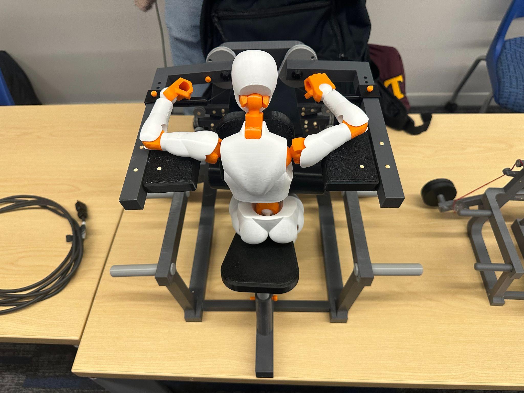
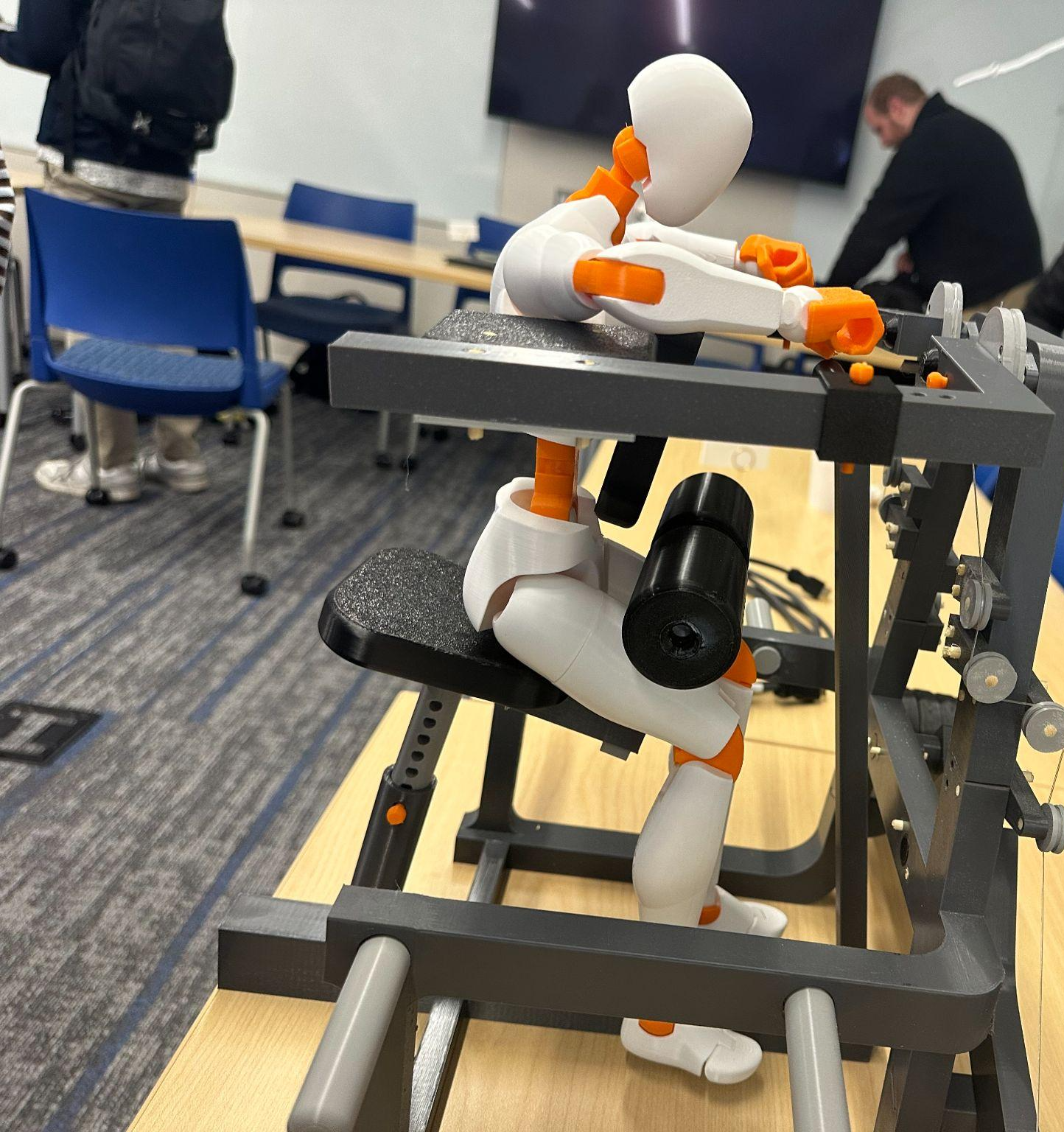
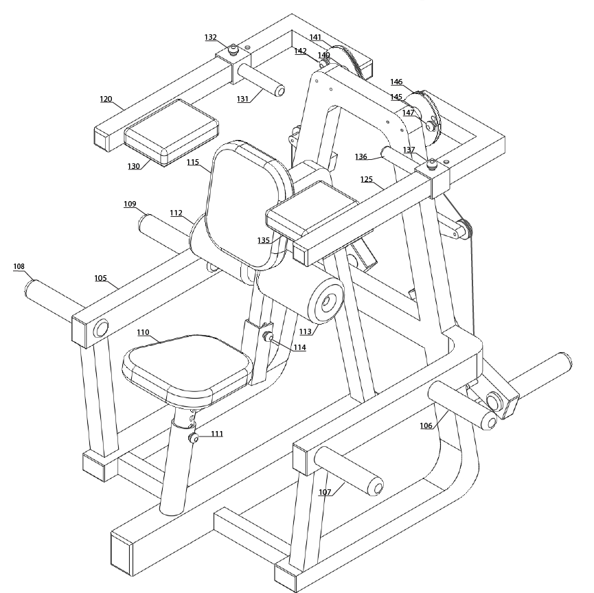
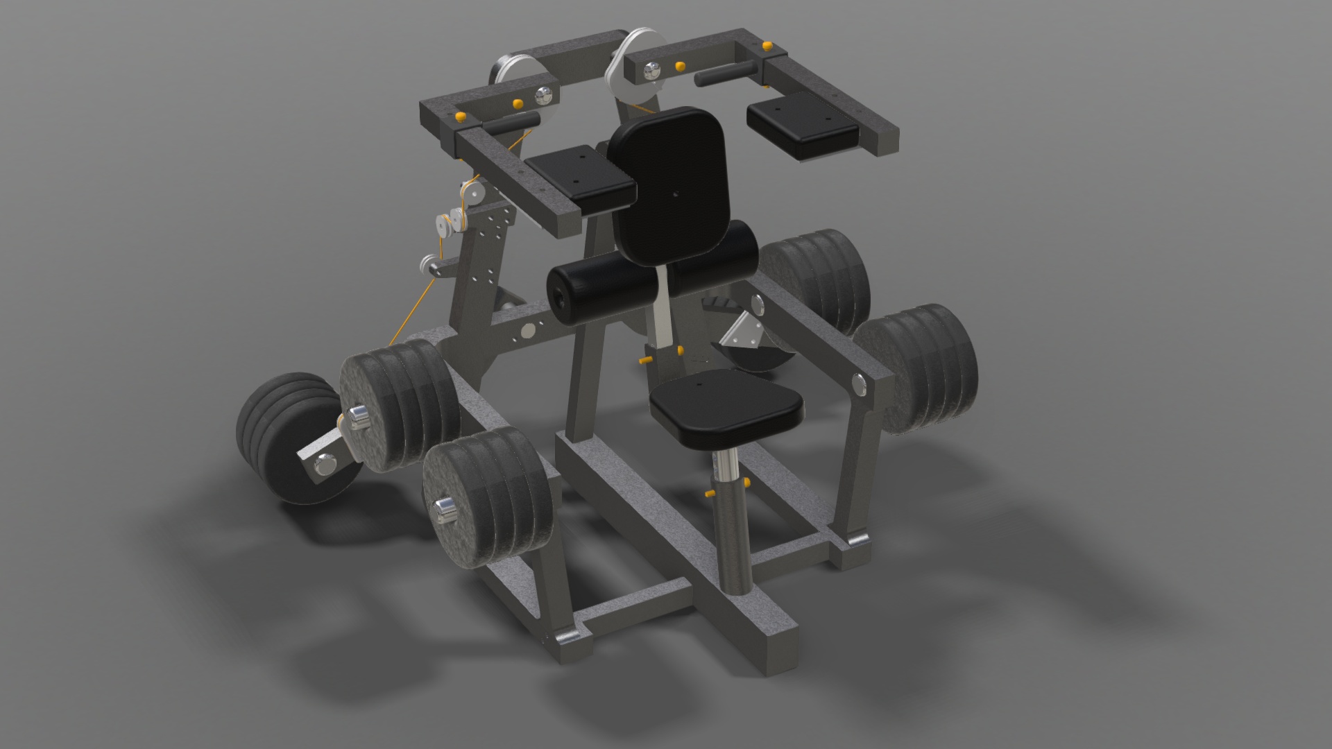
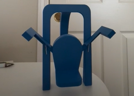
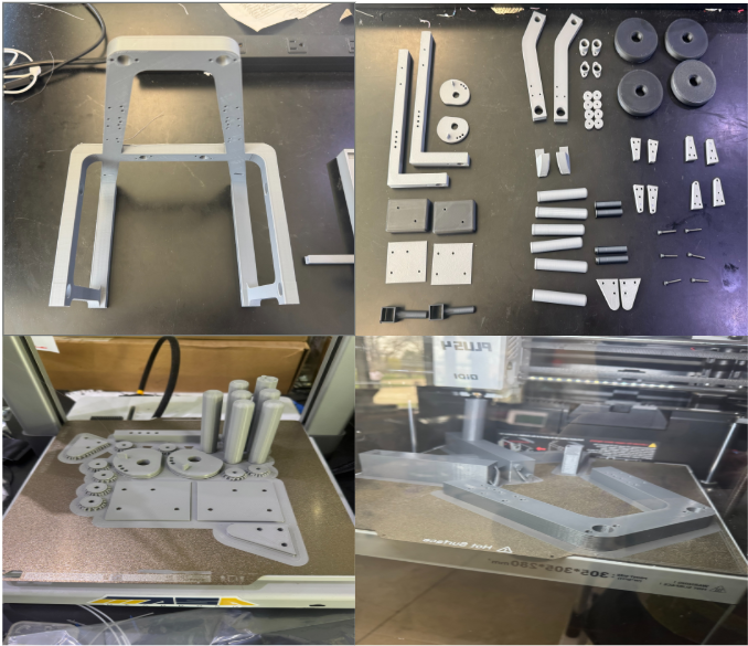
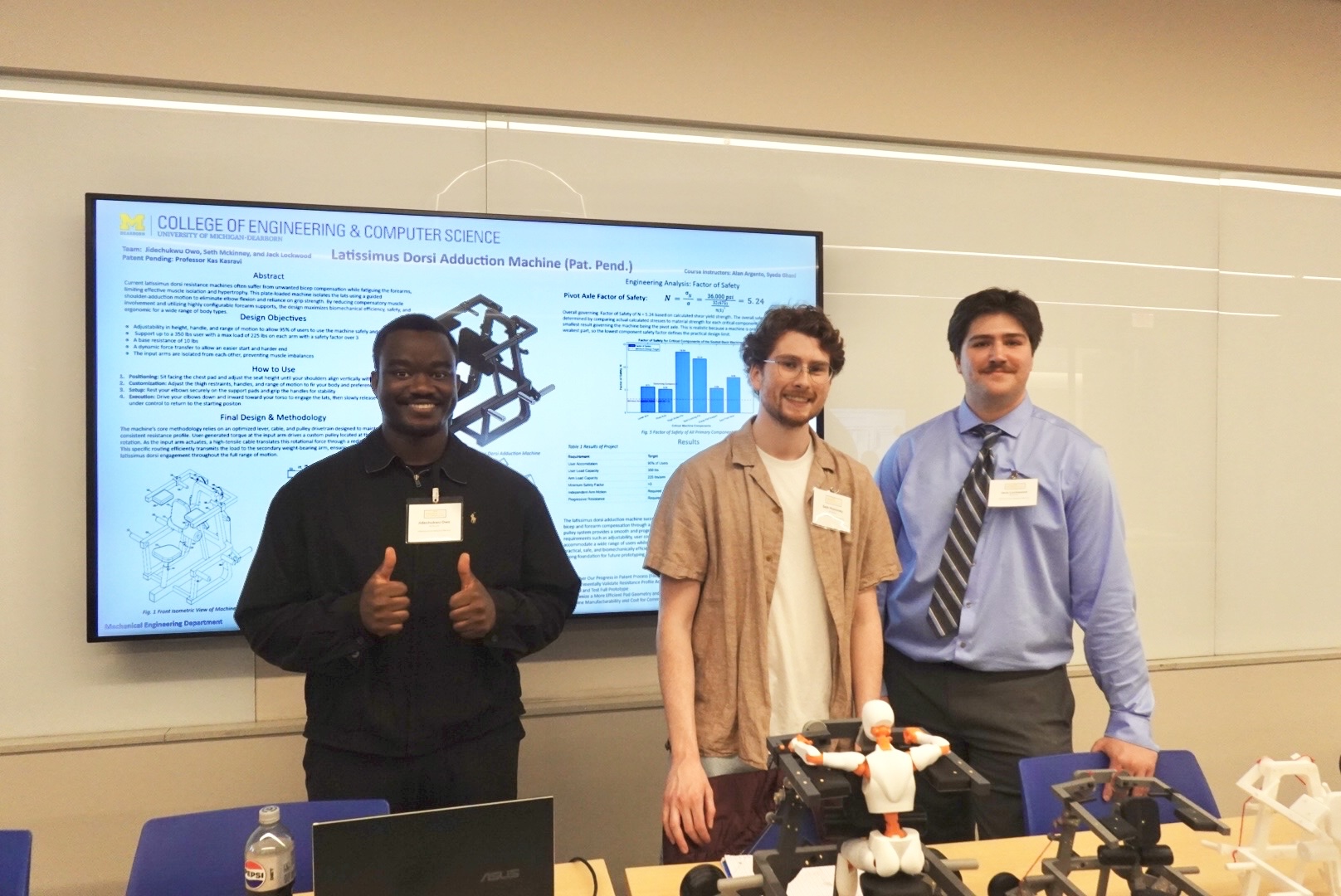
A chest-supported, iso-lateral strength machine that isolates the lats by removing grip and bicep failure from the kinetic chain. Born in senior design, now headed to market: concept → kinematics → provisional patent → four 3D-printed prototypes → redesign for manufacturing.
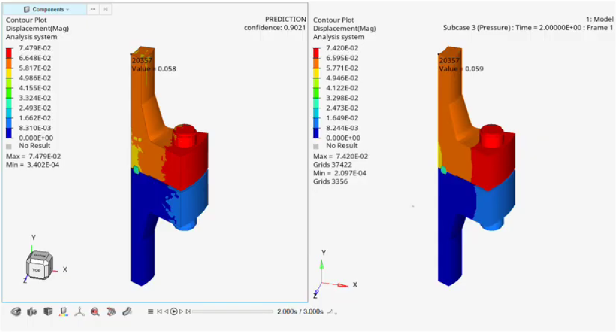
Physics-based ML model predicting stress & displacement of an O&G flanged pipe; built a 27-model morphed dataset to train it. Also produced a video tutorial series teaching customers how to use physicsAI.
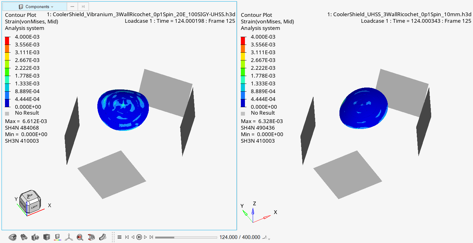
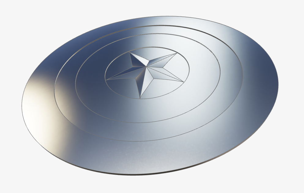
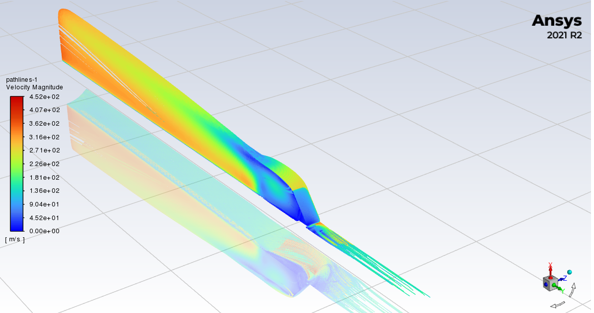
Built the shield CAD from scratch, applied a midmesh to it, then ran an explicit crash analysis evaluating the feasibility of it impacting a rigid wall.
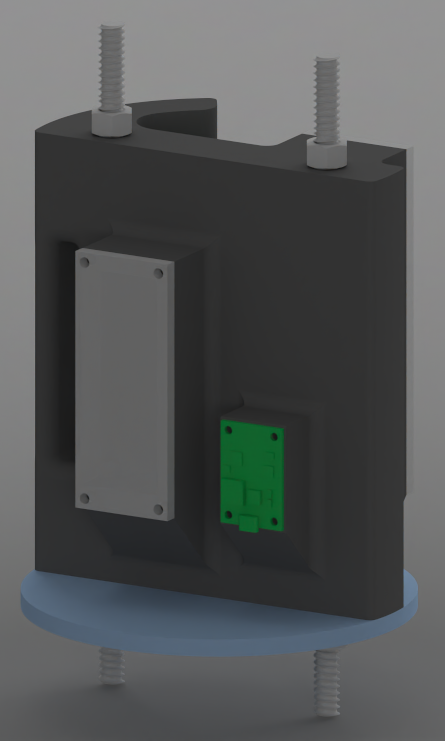
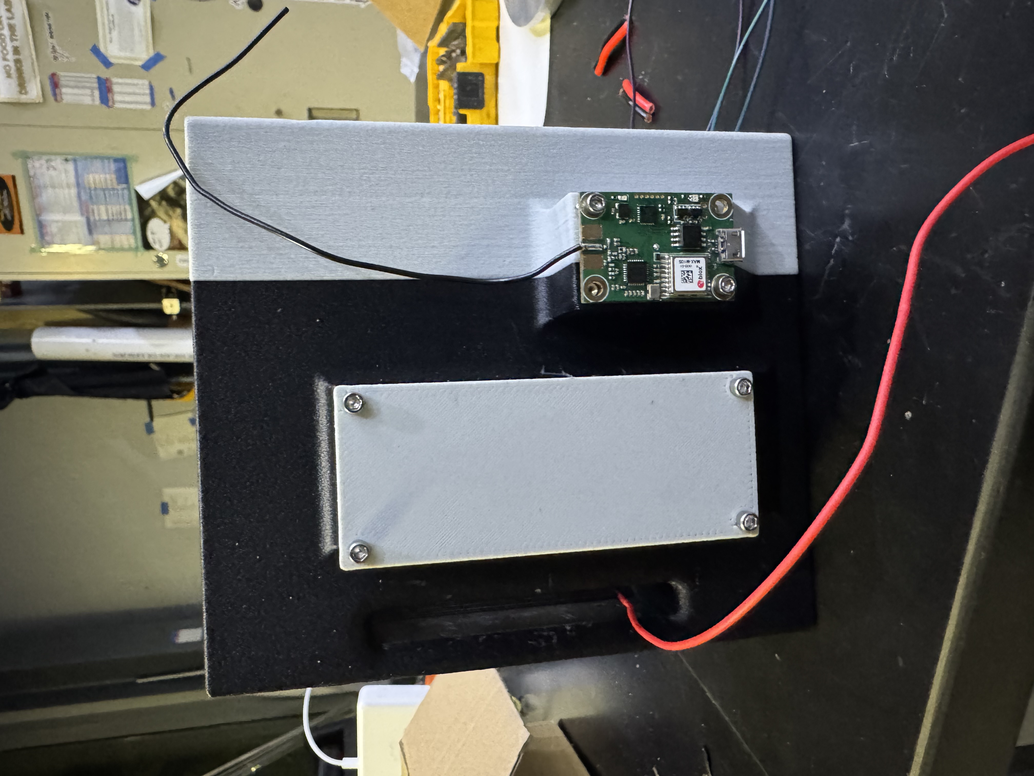
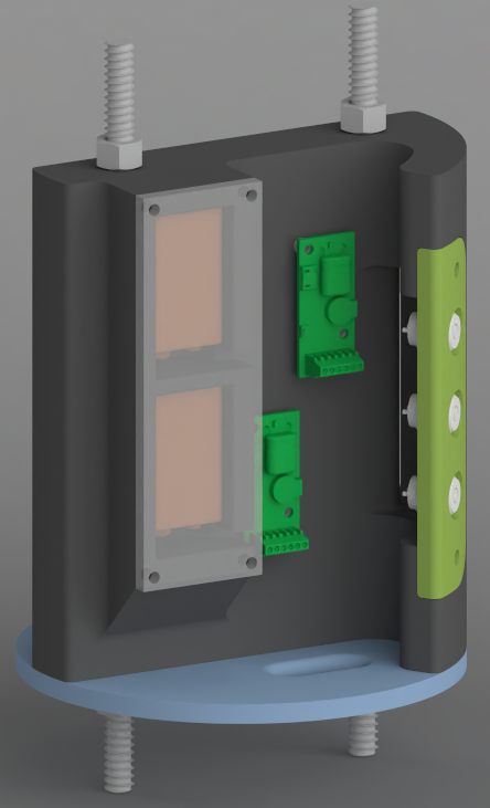
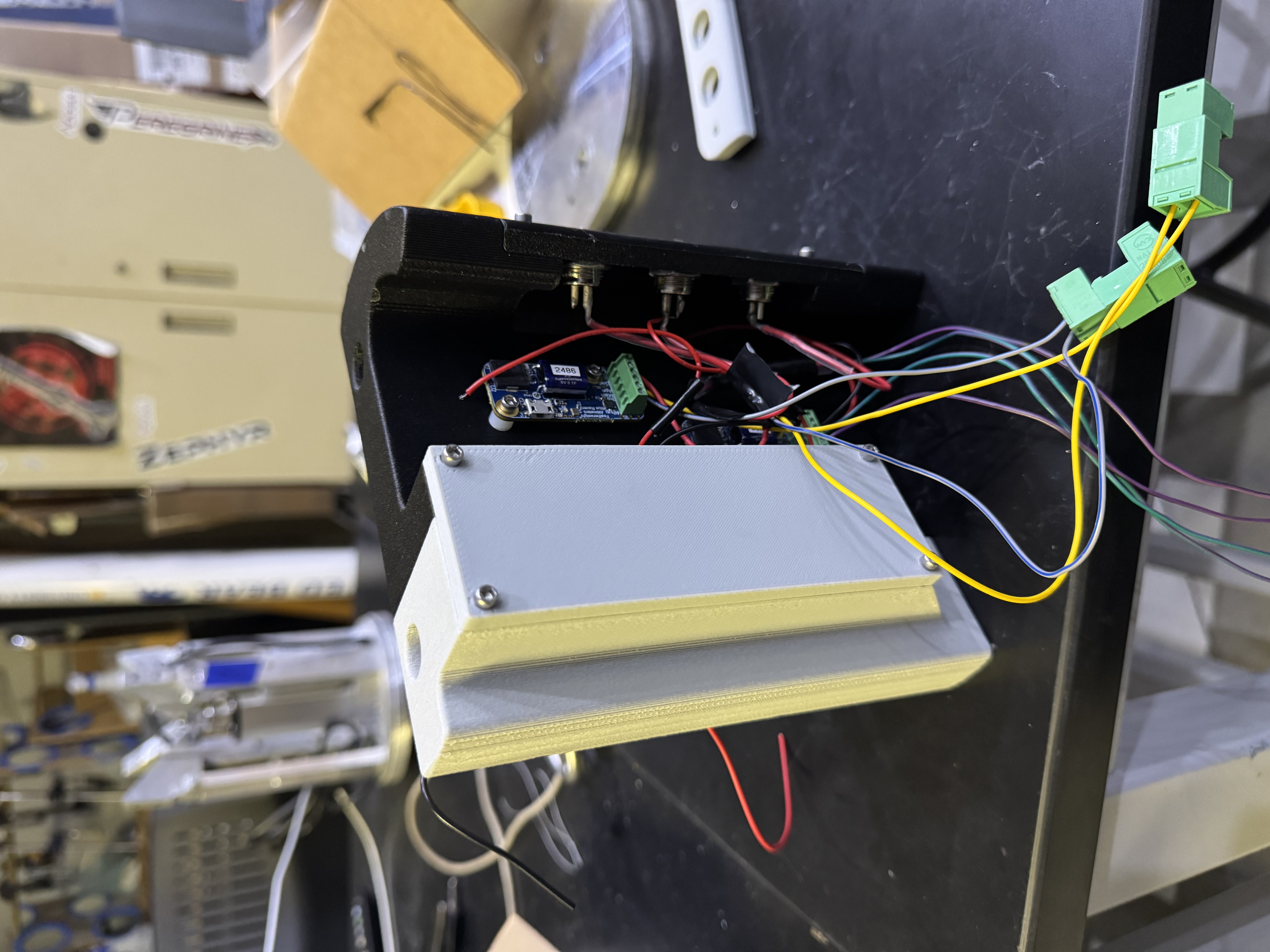
Designed, printed, and wired the recovery avionics sled flying in our team's rocket at the 2026 International Rocket Engineering Competition (IREC): dual Featherweight Blue Raven altimeters on independent 9V supplies on one face, a TeleMetrum GPS on a 21700 Li-ion on the other, and a detachable key-switch mount for ease of wiring. Hover each face to go from CAD to the printed build.
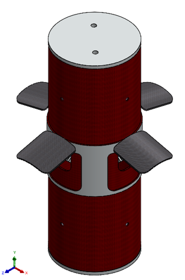
Simulated one flap at 25°/50°/75° deployment at Mach 1 in Ansys Fluent (K-ω SST, ~2.3–2.9M cells): 94 → 241 N drag and Cd 0.58–0.65 per flap, the numbers the control software uses to hit a 10,000 ft apogee exactly.
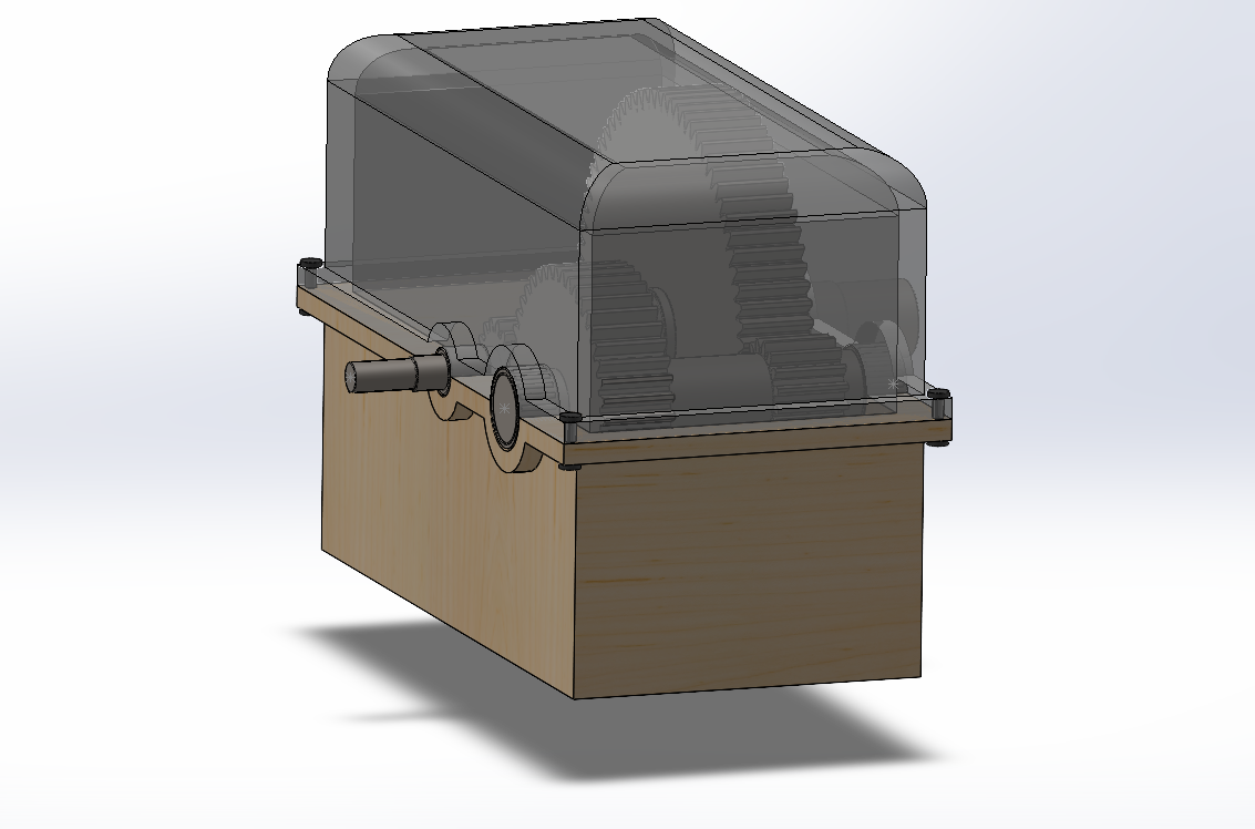
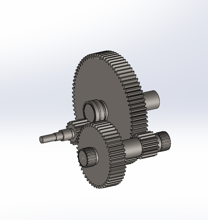
Designed & validated a 4-gear, 3-shaft, 6-bearing gearbox: MATLAB gear calcs, shaft loading, SKF bearing selection, full drawings.
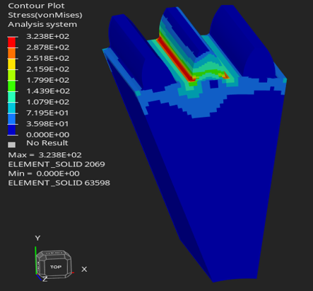
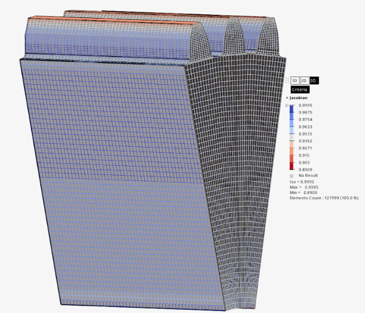
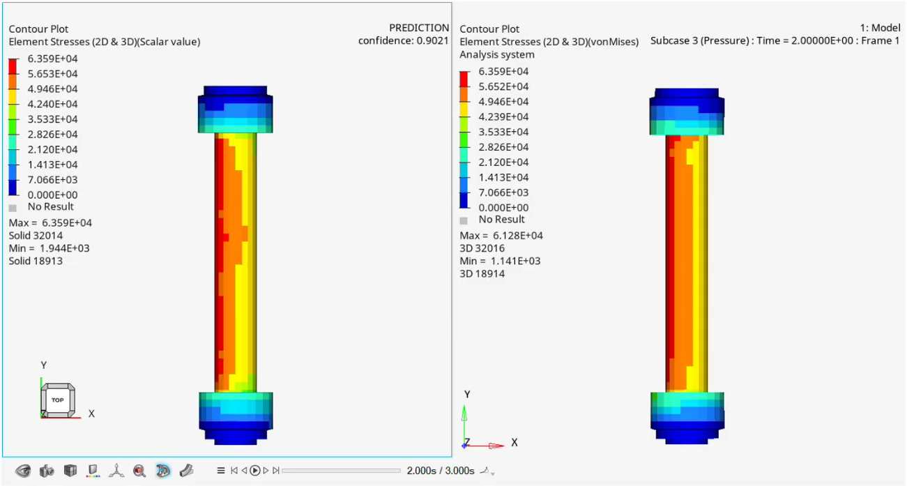
Explicit LS-DYNA study of meshing gear-tooth contact: a 900 → 128k-element mesh-independence sweep showed the coarse mesh overestimating fillet stress by >100 MPa. Geometry, not material, governed the result.
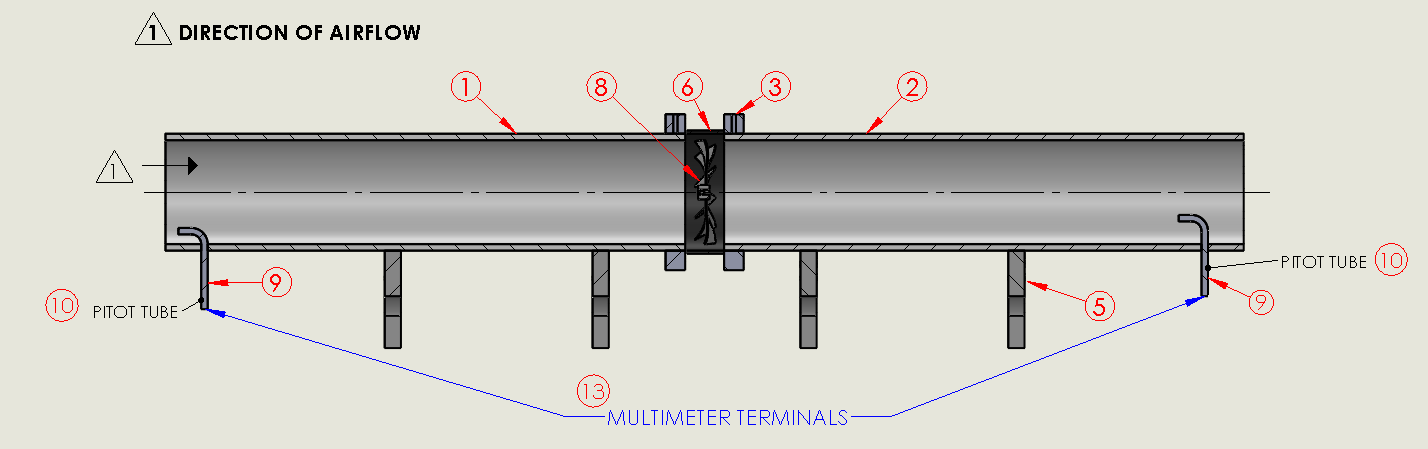
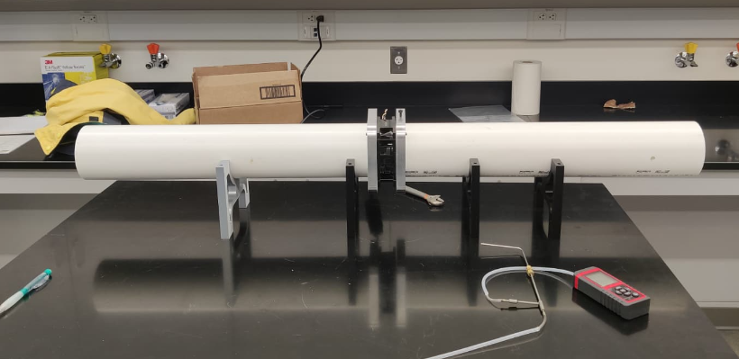
Custom duct experiment with 3D-printed blades and pitot-tube measurement. Analyzed pressure, flow, and performance across blade geometries.
Lat pulldowns and pull-ups are compound movements: your grip and biceps fail before your lats ever do. Our team designed a solution that solely trains the user's latissimus dorsi via an adduction motion (i.e., flapping), so the lats become the limiting factor of the workout, as intended. I originated the idea and am the primary inventor on the provisional patent; I also printed and assembled all of the prototypes. We're now redesigning it for ease of manufacturing as we work toward bringing it to market.
 ▶Hover to preview · click to watchTap to watch demo
Identified that secondary muscles cap lat training. Anchored the design in the "Keenan Flap": pure shoulder adduction with no gripping.
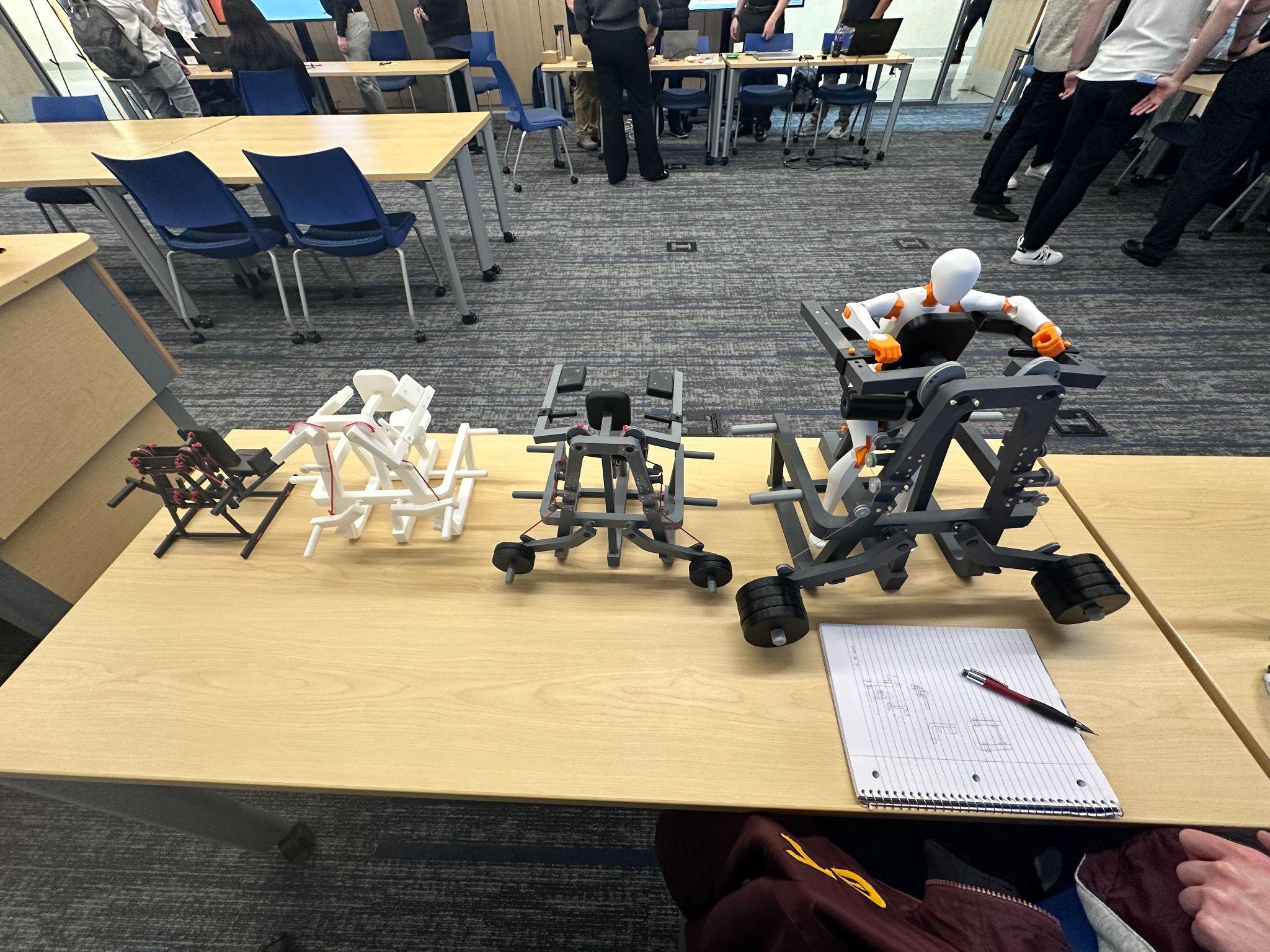
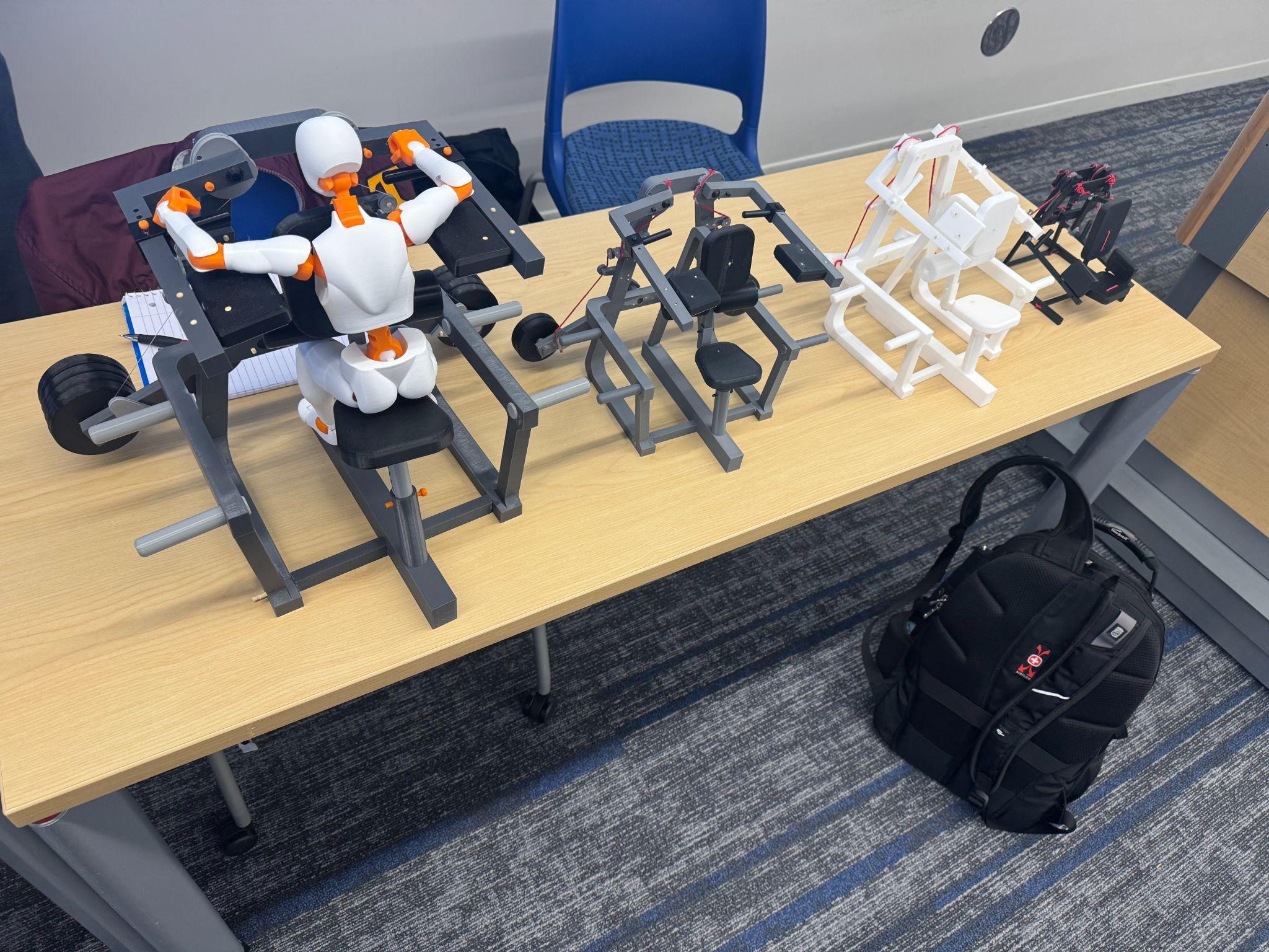
Sketches → CAD → four scaled prints compared frame envelopes, pulley locations, and pad positions to lock the chest-supported, iso-lateral concept.
Hand-calculated bending & shear at every critical joint under a 350 lb user + 450 lb payload, sizing every member with room to spare.
Filed a provisional patent on the support-system / drivetrain relationship. A redesign for ease of manufacturing is underway as we take it to market.
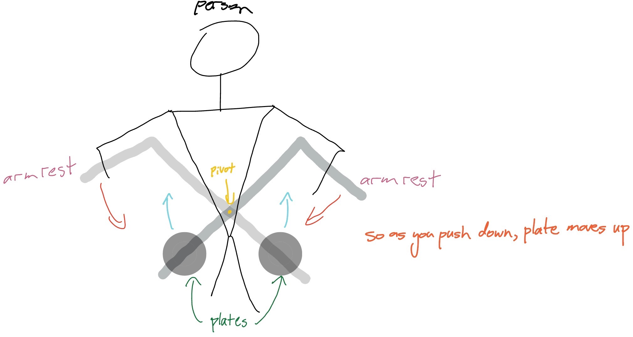
Identified that secondary muscles cap lat training. Anchored the design in the "Keenan Flap": pure shoulder adduction with no gripping.
Sketches → CAD → four scaled prints compared frame envelopes, pulley locations, and pad positions to lock the chest-supported, iso-lateral concept.
Hand-calculated bending & shear at every critical joint under a 350 lb user + 450 lb payload, sizing every member with room to spare.
Filed a provisional patent on the support-system / drivetrain relationship. A redesign for ease of manufacturing is underway as we take it to market.
The machine outgrew senior design. We're continuing the work past graduation: redesigning the frame for ease of manufacturing, working toward a full-scale build, and validating the biomechanics along the way.
I'm a mechanical engineer who likes owning the whole problem, from the first sketch to the simulation to the part you can actually hold.
Two internships at Altair put me deep in the CAE world: I built a physicsAI machine-learning model to predict stress and displacement of an oil-&-gas flanged pipe, generating a 27-model morphed dataset to train it, then taught the workflow through a video series. The following summer I supported real customer HyperMesh / OptiStruct workflows and ran an explicit crash study in Radioss. Both were presented at global, company-wide events.
Outside coursework, I co-lead recovery on MASA's rocketry team, where I ran CFD on the air-brake to help us reliably reach 10,000 ft, and I'm continuing to develop my patent-pending senior design machine, where I'm the idea originator and primary inventor.
Supported customer HyperMesh & OptiStruct workflows with the GTT ModViz Americas team. Modeled Captain America's shield in CAD from scratch and ran a Radioss crash study of it vs. a rigid wall.
Built a physics-based ML model (physicsAI) predicting stress & displacement of a flanged pipe; produced 27 morphed CAD/result datasets via HyperMorph + OptiStruct; authored a training video series.
Design, print & wire the avionics bay flying at IREC 2026: dual Blue Raven altimeters, TeleMetrum GPS, detachable key-switch mount. Ran air-brake CFD at Mach 1 across 25°/50°/75° flap angles; manufactured parachute components by hand against design-selection criteria.